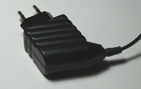
I was in search of a battery charger for a sealed lead-acid battery.
It's should have the following characteristics:
- usable for 110 and 230 V
- tolerate the fluctuations of the input voltage
- small and lightweight
- output voltage exactly 13.8 V with current limiting
 After a long search I found a switching power supply that corresponded to my conceptions.
Unfortunately I do not found a dealer for a power supply with the desired output voltages.
Therefore I opened two power supplies with different output voltages and see over both of them.
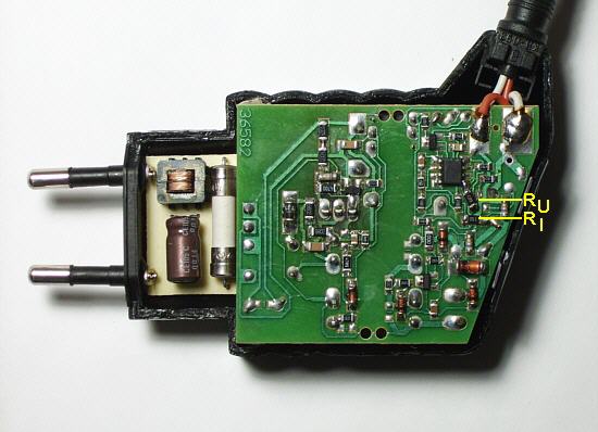
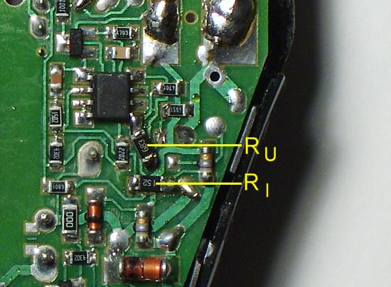
There were only in each case two different resistors. The rest of the circuit was identical.
After some trials I determined that one could change easily the output voltage and the maximum output current by exchange of these resistors.
Hooray!
Data
The manufacturer Egston published the following data:
- Mainy (switched to N2EFSW3), only old board design, see below
- Input voltage: 90 to 264 V
- Weight: 115 g
- Output power: 12 W
- Models: 9 V/1.3 A, 12 V/1.0 A, 15 V/0.8 A, 24 V/0.5 A
Note
In the meantime the production was switched to the series N2EFSW3.
The part of the circuit board, which pointing to the 230 V connection has changed.
But the half of the board on which the modification must be made, is unchanged.
Formulas
 Resting on the following formulas it is possible to tune in any voltage (between 9 and 24 V) and any maximum current (up to 1.3 A).
You should however always pay attention to the maximum power output of 12 W.
RU = 1.8889 · U - 6.3333 with RU in kΩ and U in V
RI = 4.7667 · I + 0.1067 with RI in kΩ and I in A
You don't have to calculate. There is an assistance.
Modification
 Lever out carefully the Egston sign with a screwdriver.
Pull apart both chassis-halves.
The chassis-halves stuck together at the sides.
It's a hard work, but it's possible.
Change the marked resistors on the board according to your desires.
If a parallel connection of resistors necessary, then simple solder one above the other (as a sandwich).
Glue the chassis sides again together.
Finished!
PS. Instead of a fixed resistor for RU you can solder also an adjustable one is usable.
The solder pads for it are there.
Result
For the modification I used a switching power supply for 15 V/0.8 A.
I used for RU 3 resistors (68 kΩ, 68 kΩ, 47 kΩ) parallel and so I reached an output voltage of 13.8 V.
I have checked out different resistors for the current limiting, but use now again the original resistor with 3.92 kΩ for 0.8 A, which is sufficient for my purpose.